ServoCAT Installation on my 14" TScope
I purchase a 14” TScope Dobsonian telescope
a couple of years ago and almost immediately began to look for ways to make the scope
track. Back then, I explored several
available alternatives and opted to build an equatorial platform. I chose that option because it was the cheapest
alternative and I enjoy tinkering on projects. The
details of that project can be found at: http://stevesastro.net/equipment/eqplatform.htm. I’ve used the platform ever since and it has
performed well. However, there are some
issues with the platform. It adds about
6” to the height of the scope, it has to be reset every 45 minutes or so, it is
another thing to haul around, and it requires additional setup. Of course, it also has no goto capability.
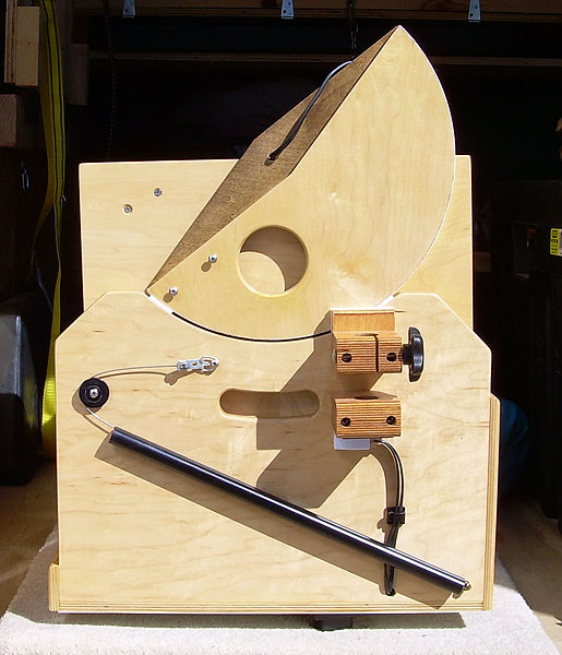
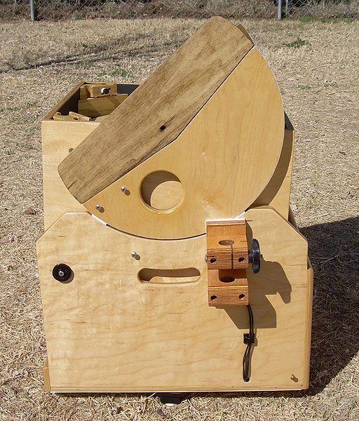
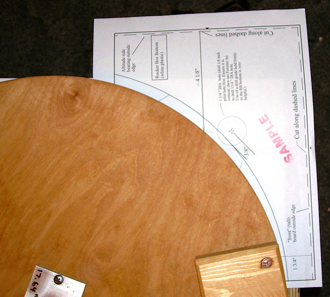
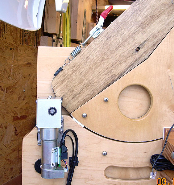
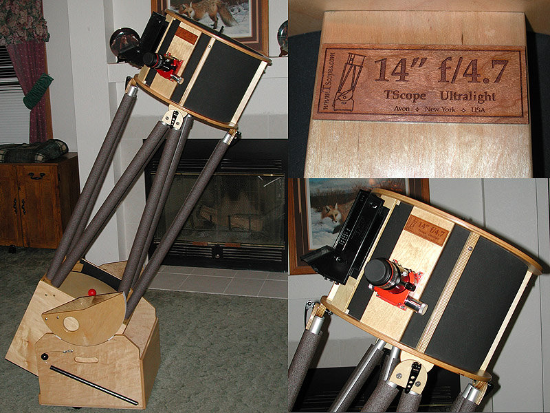
The “Cadillac” of motorized goto systems for Dobs is the ServoCAT (http://www.stellarcat.biz/). There are three components to the system. A control box, two servo motors, and a set of digital setting circles (DSCs). The system takes information from the DSCs and converts that into motion in the servo motors. When I saw a posting on the TScope Yahoo group that there was a sale going on, I took the bait and contacted Gary Myers, owner of StellarCAT. After discussing some installation issues specific to my model of TScope, I placed my order. Since I already had the Argo Navis DSC installed on my scope, I only needed the ServoCAT, motors and mounting hardware. There are two versions of the ServoCAT – standard and Jr. Since my scope is considered a small Dob (ouch!), the ServoCAT Jr. was suggested. There is no difference in capability between the two units other than the Jr. motors are smaller and have less torque available. Because some items had to be manufactured, Gary quoted me a ship date about two weeks from the order date. In the mean time, he agreed to send me an installation video so I could review it before the system arrived. I also needed the time to “correct” an issue on the altitude bearing on my TScope. The ServoCAT uses a cable drive system on the altitude bearing and the motor needs about 2” of bearing surface on either side of the motor spool. As you can see in the picture on the left, the trailing end of the TScope altitude bearing is even with the edge of the rocker box when the scope is pointed at the zenith. This wouldn’t work for the ServoCAT, so I chose to add a piece of wood to the altitude bearing as shown on the right. This would give the cable some additional surface to ride on.
 |
 |
|
Before adding the ServoCAT, I had to add an extension to my altitude bearing. On the left is the bearing before the extension was added, on the right is the bearing after the addition of the extension. |
||
The unit arrived exactly when Gary said it would. A quick check of the 60 some odd pieces showed that there were no missing parts. While there are a lot of pieces, they were all packed separately by function and clearly labeled. For example all of the azimuth drive assembly parts are in a separate plastic bag. This means that you only have a small number of parts that you are working with at any one time.
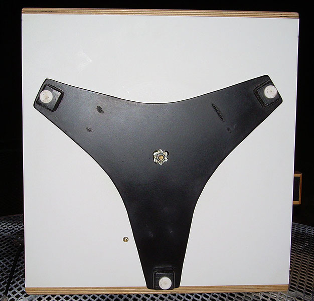
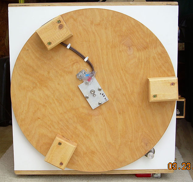
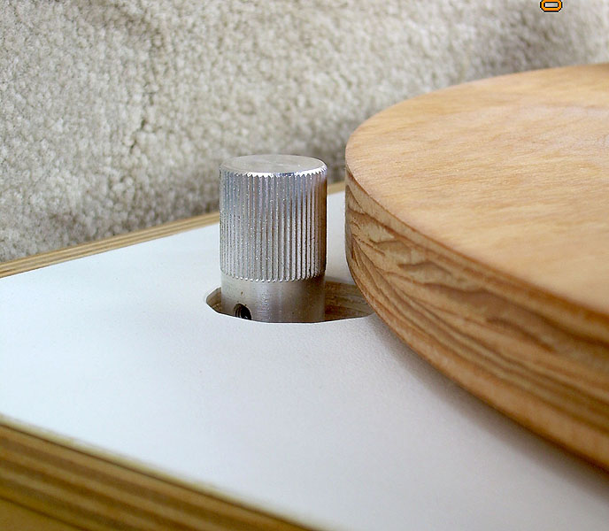
The first step was to install the azimuth drive. The ServoCAT azimuth drive is a knurled knob that runs against a round ground board (pictured in the lower right corner of the photo on the right). Since many Dobs, including mine, do not have round ground boards, I had to order one.
 |
 |
|
Because my original ground board (on the left) was not round, I had to order a new one (on the right). I opted to purchase a powered ground board. This allows you to plug in a 12-volt power source to one foot of the ground board and through a set of contacts in the center of the board routes power into the rocker box. This keeps cables from wrapping around the scope as it is rotated in azimuth. The picture on the right was taken after the entire installation was complete and shows the azimuth drive wheel already installed. |
||
To install the powered ground board (PGB) and the azimuth motor, I had to drill 4 holes in the bottom of my rocker box. Two holes are for the electrical contacts for the PGB and two are for the azimuth motor. In addition, the central hole on which the rocker box pivots had to be expanded in order to fit a new precision bushing for the scope to turn on. There is also a hole that needs to be drilled in the front of the rocker in order to install the lever that engages/disengages the azimuth motor. While this sounds a little daunting, templates are provided that help ensure the holes are drilled correctly.
 |
 |
|
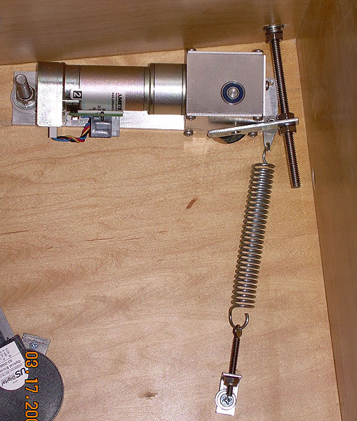
| Above: The picture on the left shows the
template for the azimuth motor holes. On the right, the azimuth motor has been
installed. The picture on the right also shows the tensioning spring that holds the motor
against the ground board and the rod going through the front of the rocker that goes to
the engage/disengage lever. Below: The picture on the left shows the knurled drive knob on the bottom of the motor. When engaged, this knob runs against the edge of the ground board moving the scope in azimuth. The picture on the right shows the engage/disengage lever on the front of the rocker box. |
||
 |
 |
|
After the azimuth motor and ground board have been installed, comes the installation of the altitude drive. As mentioned previously, the altitude motion is driven via a cable that runs against the altitude bearing. To allow this cable to pass through the Teflon pads between the bearing and the rocker, I had to cut small grooves in the Teflon on the drive side of the scope. Gary can provide pre-grooved Teflon pads for an additional charge, but I chose to do this myself. This was easily done with a dremel tool and a small cut off wheel. The altitude drive motor must be installed so the capstan on the motor is very close to the altitude bearing. This measurement is different on each scope, so no template is provided. However, the installation video covers this well and it is a simple matter of holding the motor against the scope, taking some easy measurements and then marking the 4 needed holes to mount the motor. Once the motor has been mounted, the cable drive and the altitude engage/disengage lever are installed.
 |
 |
|
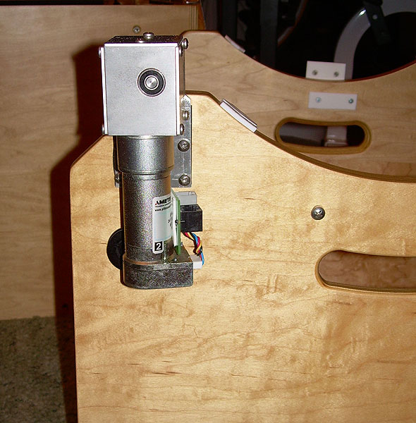
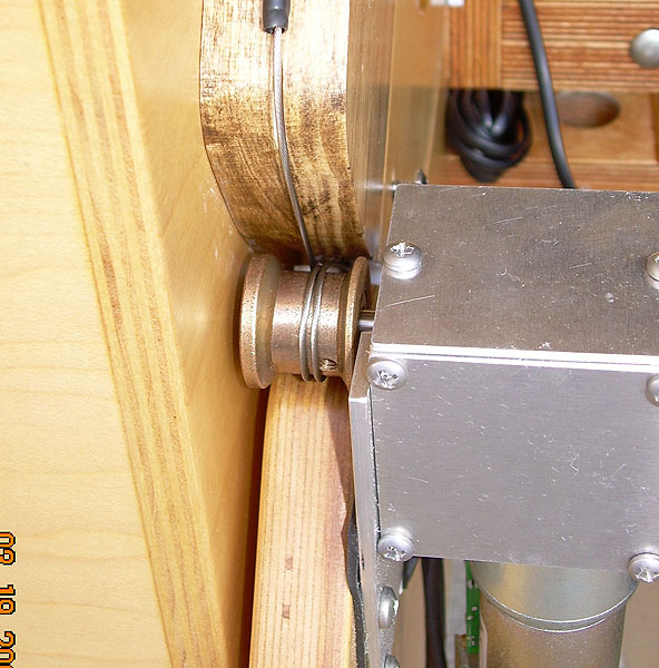
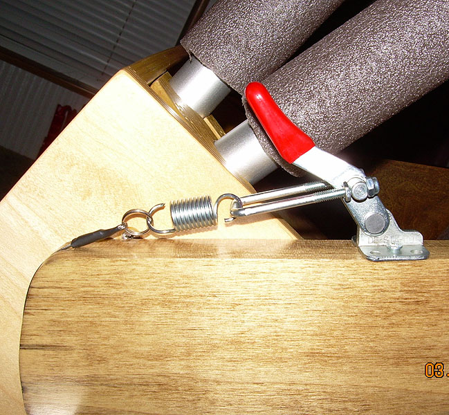
| The pictures above show the altitude motor installed (on the left) and final altitudedrive system and cabling (on the right). The altitude drive cable is fixed to the front of the altitude bearing, runs along the bottom of the alt bearing through grooves cut in the Teflon, around the capstan on the motor (twice) and then to the engage/disengage lever. Below are two more pictures showing various angles. The picture on the right shows the altitude drive lever in the disengaged position. | ||
 |
 |
|
After the altitude drive assembly is installed comes system testing and cable management. Initial testing can be done inside during daylight. Specific instructions are provided to test and troubleshoot the installation. The DSC needs to be configured to talk to the ServoCAT and the encoders need to be checked to ensure there is no slippage occurring. The ServoCAT is highly configurable and needs to be set up for your specific scope. Configuration parameters include (among other things) gear ratios, slew/jog/guide speeds, and backlash compensation. To do this, several standard configurations are provided on a CD. According to Gary, most customers can load one of the standard configurations and be done with it. Optionally, Gary can provide an AutoCal cable that can be used to configure the ServoCAT to your specific scope. This cable, coupled with included software will test your system and run your azimuth and alt motors to determine the optimal settings for your scopes gearing ratio and backlash settings. It will also help diagnose any issues regarding encoder slippage. I chose the AutoCal option and fortunately my system passed all tests. The resulting configuration was indeed very close to one of the canned configuration files.
|
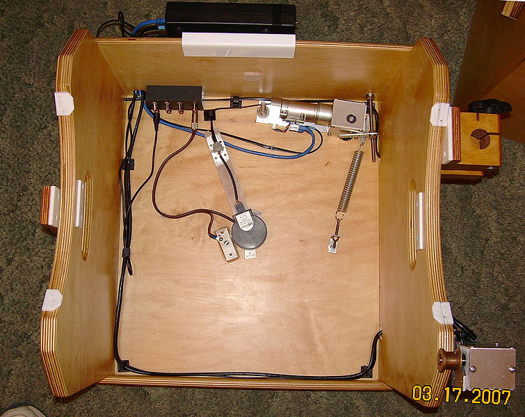
| This picture shows some of the cable routing done for the system. You can see the ServoCAT control box and its holding bracket at the top of the picture. In the upper left corner of the rocker you can see the power distribution rail (part of the powered ground board package) for controlling power to the ServoCAT, DSC, fans, dew heaters, etc. |
All told, the installation took about 8 hours over 3 days. This was taking my time with everything. I’ve had the scope out numerous times since the install. So far, the system has worked very well. Goto is accurate and tracking is very smooth. High magnification views are a pleasure, with no bumping of the scope needed to keep objects in the eyepiece. The altitude and azimuth motors can be engaged and disengaged at will, so the scope can be used motorized or not. When disengaged, the axes maintain the smooth motion they had prior to the install.