Home-made Equatorial Platform
After using my 14" Tscope for a few sessions, I decided that I wanted it to track. There are really only a few options to get a Dob to track, the Dob Driver ($700), the Servocat ($1,600, but very nice) and an equatorial (EQ) platform. Each of these have their advantages and disadvantages. I thought the installation for the Dob Driver was a little clunky. If cost were no object, I would have installed the Servocat. Unfortunately, cost is an object, so I started looking for a cheaper solution.
I did a lot of research and found that comercial EQ platforms can run from $800 to $1,500 and can take up to 6 months to have one built. I also found that many people had good luck building their own. I joined the eqplatforms group on Yahoo (I think there is a Yahoo group for just about everything these days) and began looking at plans. This helpful group has everything you need to know in order to build your own platform. After looking at numerous plans, I decided to build one myself. Here are some construction photos of my project. Click on the thumbnails for larger images.
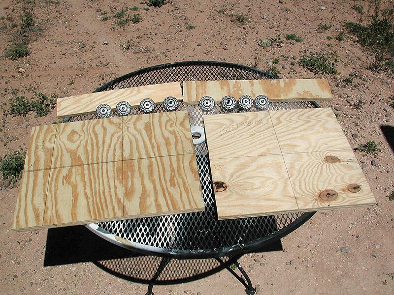 |
The raw materials. I used wheels from a pair of inline skates and 3/4" plywood to build the platform. The Yahoo Group has several good designs as well as software tools to help calculate the various curves and angles that will need to be cut. |
|
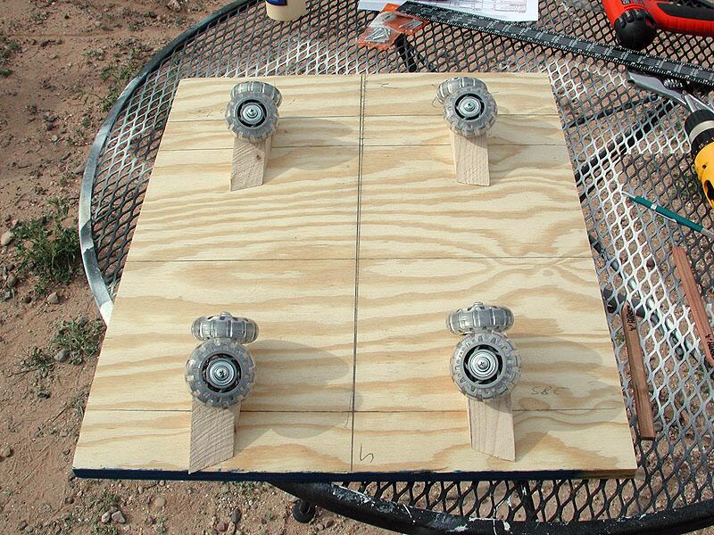 |
This is the bottom board. The inline skate wheels have been mounted at angles specific to my latitude of 32 degrees north. NOTE: These skate wheels turned out to be made of rubber that was too soft. I switched to some harder wheels part way through construction. |
|
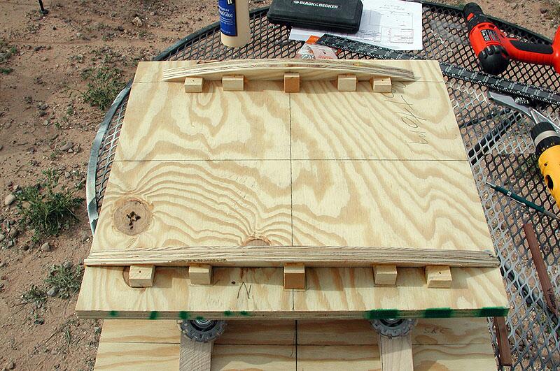 |
The bottom side of the top board. The north bearing is towards the bottom and the south bearing is on the top. The platform design I used called for the bearings to be mounted at an angle equivalent to the latitude at which the platform will be used. This angle must match the angle at which the wheels were mounted in the photo above. |
|
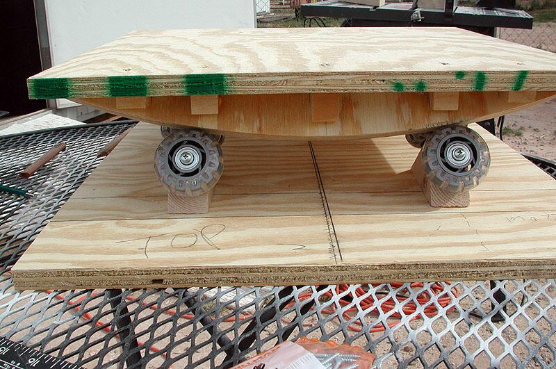 |
The raw mount. Now it is starting to take shape! You can see how the bearings and wheels work together to move the platform to counteract the rotation of the earth. |
|
 |
The drive and electronics. With the mechanics of the mount almost complete, it was time to work on the electronics. I used a surplus stepper motor with a built-in 300:1 gear reduction. The motor cost $12 and can be found here. The circuitry for the stepper motor came in a kit that needed to be soldered together. The kit can be found here. This photo was taken after I had already soldered a few components to the board. |
|
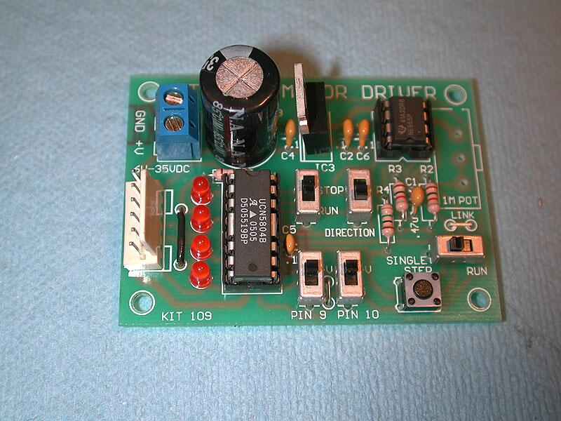 |
The final circuit board. The kit took about an hour to solder together. |
|
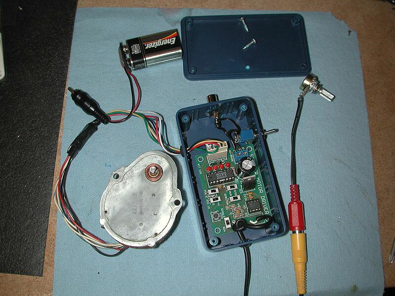 |
The circuit board and motor. I mounted the circuit board in a project box from Radio Shack. The kit has a 1 meg potentiometer that adjusts the speed of the stepper motor. This pot is designed to mount on the circuit board, however, I wired it to a long cord so I could later build a handpad that I could used to adjust the motor speed while looking through the telescope. This image shows the motor wired to the controller and a 9 volt battery being used to test the circuit. The motor came with no instructions about the wiring, but a quick Internet search turned up the diagrams here. |
|
 |
A closer view. The RCA jack on the left side of the box is the power connector. The toggle at the top turns the power on and off. Various switches on the circuit board are used to reverse the direction of the motor, half step the motor and single step the motor. The LEDs indicate which coils on the motor are being energized. |
|
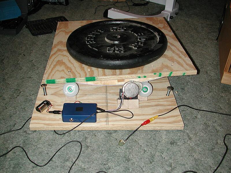 |
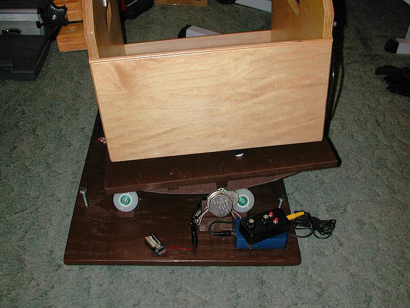
Testing the setup. The electronics have been mounted on the platform for testing. My scope weighs about 65 lbs so I've placed a 50 lb weight on the platform. The platform seems to be working well. Note that the wheels have been switched to ones with harder rubber. Also note the feet that have been added to the bottom board. They allow the platform to be leveled in uneven terrain. |
|
 |
Ready to go. Several changes here. The most obvious is the paint. I also added a bubble level and built the handpad. In addition, I put 3/4" aluminum strips on the north and south bearing faces. |
|
 |
Drive and handpad closeup. The handpad has course and fine speed adjusting knobs. It also has fast and slow buttons to help center items in the eyepiece. The circuit I used for the handpad is John Reagan's and can be found here. |
|
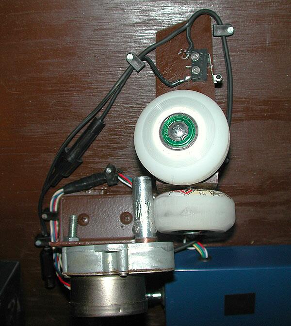 |
Drive top view and cutoff switch. The motor has a 1/2" shaft attached that drives one of the wheels. The shaft was slipping a little, so I roughed it up to give it more friction. Above the wheels is a cutoff switch that turns off power to the motor when the platform reaches its end of travel. |
|
 |
Assembled platform. This is the final platform with the rocker box from my Dob. The platform tracks very well and gives me approximately 80 minutes of tracking before it has to be reset. Resetting the platform takes about 5 seconds and the process consists of lifting the right side of the platform to rotate it back to the start position. |
|
| Final Thoughts The project took a couple of weeks to complete and was a lot of fun to put together. I probably have 25 hours of time invested and I estimate that I have spent between $120 and $130 to this point. That is far short of the cost of the various commercial solutions. The platform tracks very well. Objects remain in the field of view of a high power eyepiece even after 30 minutes. The handpad is a nice feature and works wonders when centering objects. There are two drawbacks to my platform. First, the platform adds about 6 inches to the height of my scope. This means that when viewing at the zenith, I now need a small step to reach the eyepiece. Second, and more significantly, even with the harder wheels, the scope is a little bouncy. Tapping the eyepiece induces a vibration that takes about 4 seconds to dampen and stop. Even with these issues, I'm happy with how the platform performs. Viewing objects at high power without having to constantly nudge the scope is awesome! |